Introduction
To supply easy to use, ultra-realistic simulation products that are attainable to the average flight sim hobbyist yet suitable for the most demanding professional application. These tools shall provide pilots and instructors with true-to-scale form and function with precise tactile feedback when used for teaching and practicing aeronautical skills.
Noble Flight Simulation, LLC (NFS) was started with altruistic motives to provide a solution for the rusty pilot at home. Flight proficiency is a topic that is often discussed in the aviation industry and that’s because flying is a skill that requires practice; especially instrument flying. Noble Flight Simulation endeavors to provide the most realistic one-to-one simulation experience so that the workflow matches the actual aircraft.
It is our vision that flight proficiency can be maintained by regularly practicing at home with our products. It will be used to build confidence, try out new scenarios, and be a practical trainer that will be used. To that end, our design philosophy centers around ease-of-use. We understand that the pilot doesn’t necessarily want to spend time with configurations, computer specifications, and adjustments; the majority just want things to work and to get the time in.
Noble Flight Simulation Team
Tyler Noble, D.O. - Tyler, the founder of Noble Flight Simulation, LLC, has always been fascinated with aviation. He obtained his private certificate in 2003 followed by his instrument rating the following year. After earning his Bachelor's degree from Virginia Tech, he attended medical school where he calls upon his engineering background as a joint replacement surgeon. Tyler believes that great customer service is the most important quality a business can possess.
Austin Fang, Ph.D. - Austin’s background is in Mechanical and Aerospace Engineering. He is also a pilot and obtained his private certificate in 2003 with and an instrument rating in 2020. Austin earned his Bachelor’s degree and Masters of Science degree in Mechanical Engineering from Cornell University. He worked at Sikorsky Aircraft Corporation for 10 years where he was responsible for vibration and acoustic reduction. He was a recipient of a full scholarship in Sikorsky’s continuing education program which resulted in a second Masters of Science degree and a Doctorate, both in Aerospace Engineering. His experience traveling the world and fixing rotorcraft issues shaped his attitude towards customer service. Customer requests are treated like an aircraft on ground (AOG) situation deserving the time and resources required to fix it quickly and efficiently.
Hardware Overview
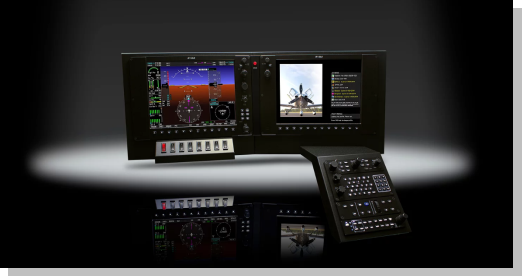
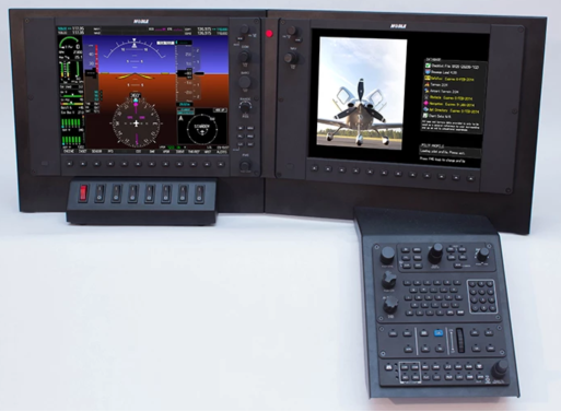
NFS provides hardware solutions to simulate the G1000 and the Cirrus Perspective avionics suites. The hardware is designed to be a one-to-one replica of the actual Garmin system. The separate components are as follows:
Primary Flight Display (PFD)
The PFD contains multiple encoders and buttons. There are twelve (12) softkey buttons aligned on the bottom of the display. The PFD contains the encoders for the COM portion of the NAV/COM radios.
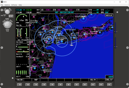
Multi Function Display (MFD)
The MFD also contains multiple encoders and buttons. There are twelve (12) softkey buttons aligned on the bottom of the display. The MFD contains the encoders for the NAV portion of the NAV/COM radios.
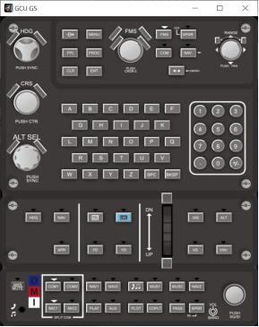
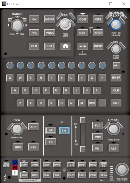
Center Console Unit (CCU or GCU)
The CCU also known as GCU houses the keyboard, keypad, autopilot, and audio panel buttons and encoders. It is the central interfacing unit for the Cirrus Perspective avionics system. The pilot can use the CCU to complete most tasks in an efficient and safe manner.
Auxiliary switch panel (panel mounted units only)
The auxiliary switch panel contains 8 of the most commonly used switches.
For Prepar3D flight simulator, they are (from left to right):
- 1) Master Battery (BAT1 and BAT2)
- 2) Alternator 1
- 3) Alternator 2
- 4) Master Avionics
- 5) NAV Light
- 6) Strobe Light
- 7) Landing and Ice Light
- 8) Pitot Heat
Software Overview
The NFS Simulation Software strives to behave exactly like the real avionics. The goal is to be able to work through the procedural steps at home on the simulator as one would in the cockpit of a Cirrus aircraft. To that end, we built our software from the ground up in a modular fashion to simulate all Line Replaceable Units (LRUs) that exist in the Cirrus aircraft. We have also split out our code into different logical coding layers. For example, the code to interface to a flight simulation software like Prepar3D or XPlane 11 is not integrated into the code to display the components on the PFD or MFD. This separation allows for flexible code architecture and allows us to support future changes in flight simulation.
Requirements
The requirements for NFS hardware and software are listed below:
- 1) A computer capable of running a flight simulation platform such as, Prepar3D v4 or above, or XPlane 11 or above.
- 2) The computer will require a graphics card capable of connecting the PFD and MFD video signals. (we provide VGA to DisplayPort cables to facilitate the connections)
- 3) The computer will also need a free USB port to connect the USB cable from the back of the MFD.
- 4) The PFD, MFD, and onboard circuitry all require power going to the wall outlet or a surge protector power strip. There are a total of three plugs required.
- 5) To run our software, the flight simulation requirements exceed NFS’s requirements. If the computer is capable of running a flight simulator, our software will run without issues.
NFS recommends a computer with the following specifications:
- CPU: Intel i7 7700K or above
- Memory: 16 GB of RAM
- Hard Drive: At least 20 GB of free space available
- Graphics Card: nVidia GeForce 980 or above (with three open ports for the main screen, PFD, and MFD. The PFD and MFD are DisplayPort connections.)
Note: NFS has partnered with Jetline Systems and can help recommend a custom built PC. Please contact us for details.
Hardware Setup
Your panel mounted NFS G1000 CP unit comes 95% assembled in a custom foam mailer. To complete assembly, the dropdown GCU panel needs to be secured in place. To do this, please follow the steps below.
Note: If you did not purchase the optional panel mount or if you elected to have the unit shipped disassembled to save on shipping, you can find a detailed video showing how to assemble the unit here: this video shows our older style of cable clip. The preferred method of assembly is to complete PFD and MFD assembly and install the GCU mount last.

Securing the GCU Center Console
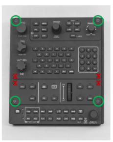
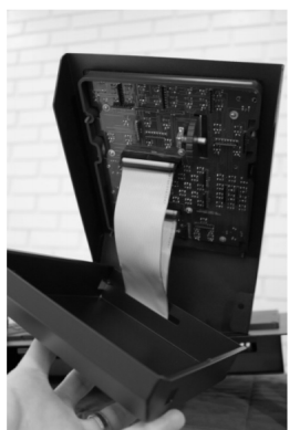
- 1) Remove the GCU center console from the GCU metal panel mount by removing the 4 corner screws (5/64” hex) and metal backing. NOTE: The non-G6 perspective console has 8 screws. The 4 central screws are “dummy” screws for aesthetic purposes and do not need to be removed. (Figure 1).
- 2) Place the unit at the edge of your work surface so that the empty GCU mount can be bolted in place using the provided Philips head screws. Flip the GCU ribbon cables out of the way to expose the two mounting screw holes.
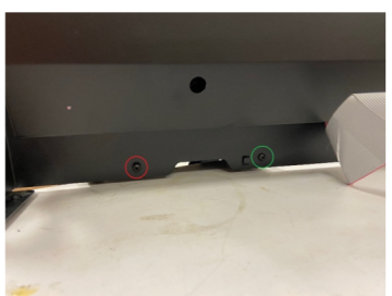
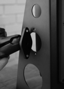
- 3) Referring to Figure 2, tighten the more central screw (green circle) completely while leaving the outside screw (red circle) loose.
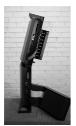
- 4) Flip the unit on its side allowing the GCU mount to act as a “kickstand” as shown in Figure 3.
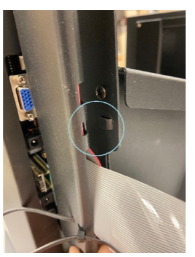
- 5) The cable clip is used to secure the ribbon cables in place. Locate the finger-tab locking mechanism shown by the light blue circle in Figure 4.
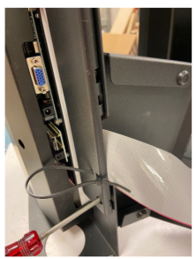
- 6) Slide the locking tab into the slot. The cable clip will also slide over the head of the second mounting screw that was left loose in Step 1.
- 7) Tighten the second screw to secure both the GCU mount and cable clip in place (Figure 5).
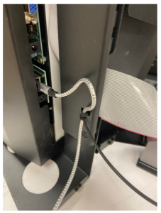
- 8) When the time comes to connect the micro USB cable, the cable must be tethered to avoid accidental damage should the unit be moved without unplugging the cable (Figure 6)
- 9) Place the unit upright and replace the GCU console in the panel mount. Connect the two ribbon cables as shown in Figure 7 and then replace the metal housing.
Ribbon cables flipped out of the way to expose holes
If you are installing the unit in a custom panel and would like to control the backlight brightness directly, you can connect a 50k linear taper potentiometer to the green 3 pin terminal on the top right corner of the interfacing board mounted within the MFD. Should you choose to do this, the potentiometer “wiper” goes to the center terminal and your hardware will require a firmware re-flash.
Please see the Section: Flashing Your Firmware.
The NFS G1000 CP panel mount has a bolt pattern on both the left and right ends to accept the RAM® diamond ball base iPad mount (Figure 8). The holes are tapped for #10-32 bolts.
Final Hardware Setup
Each monitor panel (MFD and PFD) has its own video cable and 12V power supply with a 5.5mm plug. The microcontroller mounted in the MFD uses a micro USB cable and a 5V power supply with a 3.5mm plug.
Two right angle video adapters are provided to allow clearance for the video cables. When plugging in the video cables, ensure that the cables are fully seated and secure the thumb screw to hold everything together.
Note: The USB cable should be plugged in LAST. If you plug in your USB before the video and power cables, the hardware may become unresponsive requiring a reset by unplugging the USB.
 Warning: The Micro USB jack can be damaged if the cable gets pulled. To avoid this damage, the USB cable must be tethered to the panel mount as described in the hardware setup section. Damage as a result of not tethering the USB cable properly is not covered under warranty.
After making your final connections to a running PC, your unit backlighting will illuminate. Plugging in the USB cable will also automatically send a “power on/off” signal to the LCD displays.
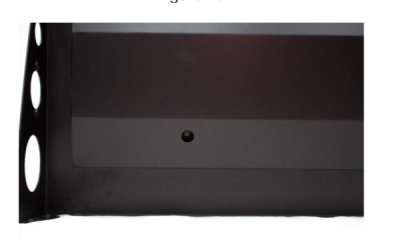
The LCD power button is the flush button at the bottom left of the bezel. To turn the LCD displays on or off, press and hold the power button for 2 seconds.
A quick press and release of the LCD power button triggers the LCD picture auto adjust feature described below.
Note: The LCD display power is controlled by the unit’s microprocessor. In order for the power buttons to function, the USB cable must be connected to a running PC.
The PFD and MFD monitors need to be configured within the windows environment to ensure the software is able to send the images to the correct LCD. There are several places to do this, however it is best to do within your graphics card settings. The same setup video referenced earlier (provided again below) walks you through the process of how to configure and position multiple monitors within the windows environment. Please watch starting at 14:30.
The MFD and PFD displays need to be set to a resolution of 1024x768 with a refresh rate of 70Hz. If the screen refresh rate is not set properly, you may notice a progressively widening halo around the outside of the screen viewing area (Figure 9). If this occurs, please recheck your monitor settings and the problem will resolve once the resolution and refresh rate have been corrected.
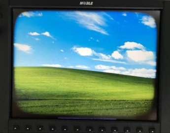
Occasionally when NFS G1000 software launches, some of the image can be just outside of the viewing angle. This is most noticeable for the NAV and COM frequencies. If this occurs, simply press and release the flush LCD power button to trigger the screen auto adjust feature and re-center the image.
Flashing the Firmware
From time to time, there will be upgrades to the hardware that require users to re-flash the firmware on the unit. A firmware reflash should not be needed on a routine basis and should only be done if instructed to do so by NFS support. The process is easy as described below:
- 1) Download and install the firmware bootloader application located here:
- 2) Open the boot loader application and load the firmware .hex file by going to “File” → “Open HEX File”.
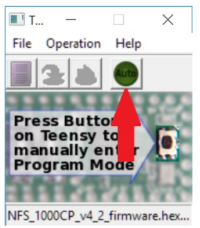
- 3) Ensure the green “AUTO button” on the bootloader application is enabled (located immediately below the "Help" tab. Please note that by default the green auto light is OFF (as shown by the red arrow in Figure 10 below)
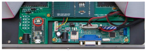
- 4) To initiate the reboot, press the physical hardware button located on the processor board located in the back of the MFD (red circle in Figure 11). For convenience, there is a circular cutout in the sheet metal backing to allow the re-flash button to be pressed with a non-metallic object such as a pencil eraser (Figure 12).
Using the Hardware
The panel mounted NFS G1000 CP unit has two displays; the PFD and the MFD. There are two flush mounted power buttons on the bottom left portion of each display. Please refer to Figure 13 below where the red circles show the location of the power buttons.
A long press of the flush mounted power buttons will toggle the displays on and off. Once powered on, a short press will invoke the auto calibration feature for the displays. It will center and adjust the display to fit within the bezel.
Warning: If the flush mounted power button doesn’t pop back up fully after pressing, it will continuously send a signal and block several other buttons (but not all) from registering. Please ensure that the flush button pops back flush after each press.
Software Setup
Thank you for choosing Noble Flight Simulation’s Cirrus Perspective unit! Our NFS CP Pro software comes with the hardware you purchased. This chapter will provide instructions for how to download and install the software. Additionally, the process to obtain and install future updates will be explained.
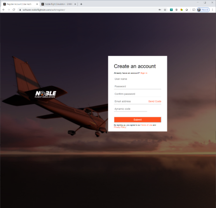
Registering an Account
You will need to register on our software website located here:

Downloading the Software
Once your account is registered, you can select the software product listed on the main page.
- 1) Choose “NFS CP Simulation Professional For P3D” or “NFS CP Simulation Professional for XPlane11”.
- 2) Click “Buy Now”
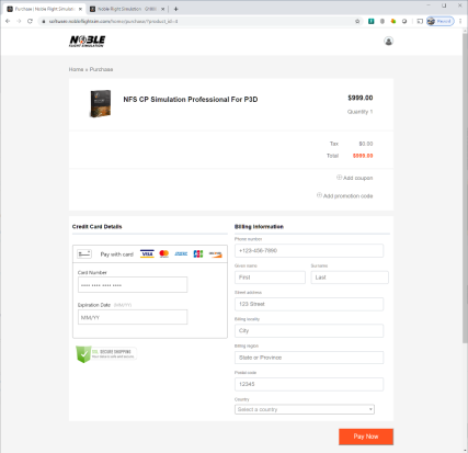
- 3) In the Product Detail page, please select “Buy now”. It will take you to the Purchase cart where you can enter the billing and credit card details (Figure 16).
- 4) Once all the information is entered, please press “Pay Now”
- 5) A serial number will be provided in the next page. Please copy down or Please copy it down or copy it in Windows using CTRL+C.
Note: Please be careful in selecting the correct flight simulation software (i.e. P3D and/or XPlane 11).
Note: If a coupon code was sent to you, please enter it by selecting the “+ Add coupon” symbol. If the total is 0 dollars, a credit card is not required to check out.
Installing the Software
- 1) Upon download completing, you can double-click the installer. It will take you through the End User License Agreement (EULA) and the choice of installation directory should you opt to change it from the default path.
- 2) Once the software installs, it will automatically run the first time. You will be asked to enter an activation code. Please enter the serial number copied from earlier. If you copied it using Windows, you may paste it here using CTRL+V.
That’s it! Our program is designed to be simple and easy to use. When starting the software each time, it will automatically sync with P3D or XPlane 11 upon startup.
Note: Some computers do not automatically install the correct USB drivers. If WinUSB drivers are not installed correctly, the program will crash to desktop when buttons associated with LED lights are pressed. To ensure that WinUSB drivers are installed a one-time check is required. Please see the section labeled “WinUSB Driver Installation”.
WinUSB Driver Installation
WinUSB drivers is required for full compatibility with LED lights and dimmable backlighting. Please ensure WinUSB drivers are downloaded and installed for the hardware. The WinUSB utility can be found here:
- 1) Upon opening, please locate:
- 2) Right-click the correct device and select "Install WinUSB" (You may get a warning about installing an unsigned driver. Please go ahead and install.)
- 3) If you get a timestamp error, please ensure you are connected to the internet.
- 4) Once the device changes to say:
- 5) You can close the application.
The driver installation is complete.
Running the Software
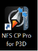
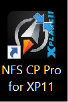
Our program was designed for simplicity for the end user. Upon double-clicking the NFS software program icons (Figure 17 and Figure 18), the PFD and MFD displays will be found and the program will automatically load in full-screen mode. The next step is to start the flight simulation software. Our NFS software program will automatically connect with Prepar3D and XPlane behind the scenes and the flight data should begin to show on the PFD and MFD screens.
Using the Software
The NFS Cirrus Perspective Simulation software will display the bezels when in windowed mode (Figure 19, Figure 20, Figure 21, Figure 22). A GCU (either G5 style or G6 style) rendering also pops up upon launching the software. These renderings allow the user to use a mouse or a touch screen to interface with our software.
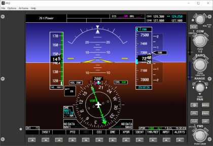
When using in conjunction with our NFS hardware, a simple double-click on the display area or selecting “Full Screen” under “Options” will maximize the program into fullscreen mode and remove the bezel borders.
Software Options
The user can set certain options by double-clicking the display to enter windowed mode and select Options in the windows menu above (Please refer to Figure 23).
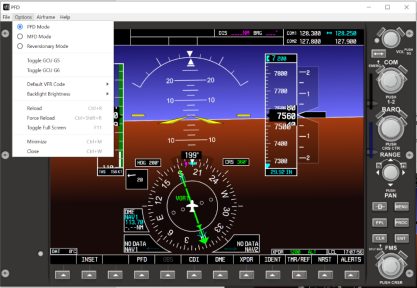
Display Modes
Any window can be set to either the PFD, MFD, or Reversionary display.
Toggle GCU
This section allows the showing of the G5 GCU or the G6 GCU
Default VFR Code
This allows the user to select 1200 or 7700 as the default VFR transponder code when one pushes “VFR” in the softkey menu.
Backlight Brightness
This option allows the user to set the backlight on the hardware units.
Display Options
The user can select to Reload, Force Reload, or Toggle Full Screen. The Reload and Force Reload options shouldn’t be necessary for most scenarios.
Software Features
The software will simulate the following:
PFD Controls
- COM VOL knob
- MENU button
- COM Swap button
- FPL button
- COM frequency knob
- PROC button
- Baro knob
- CLR button
- Range knob
- ENT button
- DIRECT TO button
- Softkeys 1-12
Middle Bezel
- Reversionary Button
MFD Controls
- NAV VOL knob
- NAV frequency knob
- NAV Swap button
- Softkeys 1-12
GCU Controls
- HDG knob
- Multi-function knob (FMS default)
- CRS knob
- FMS button
- ALT SEL knob
- XPDR button
- DIRECT TO button
- COM button
- MENU button
- NAV button
- FPL button
- Swap button
- PROC button
- Range knob
- CLR button (hold to return to map)
- ABCD keyboard
- ENT button
- Numeric keypad
Autopilot Controls
- HDG button
- Trim Wheel Down
- NAV button
- IAS button
- AP button
- ALT button
- FD button
- VS button
- Trim Wheel Up
Audio Panel Controls
- COM1 button
- MIC1 button
- COM2 button
- MIC2 button
- NAV1 button
- NAV2 button
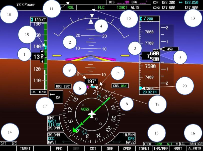
PFD Operations
The PFD contains:
- 1) Airspeed Tape
- 2) Attitude Indicator
- 3) Altimeter Tape
- 4) Slip/Skid Indicator (ball)
- 5) Vertical Speed Indicator
- 6) Track Diamond
- 7) Turn Rate Indicator
- 8) Horizontal Situation Indicator (HSI)
- 9) Magnetic Compass Heading
- 10) Power percentage
- 11) Navigation Status Box
- 12) Map Inset
- 13) COM1/COM2 Frequencies
- 14) OAT gauge
- 15) Transponder setting
- 16) Clock
- 17) Wind Direction
- 18) Heading Reference Bug
- 19) Airspeed Reference Bug
- 20) Altitude Reference Bug
Note: Please refer to the Garmin Pilot’s User’s Guide for more detailed information
PFD Functions
The PFD functions simulated include:
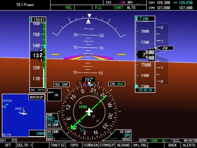
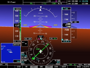
Inset Map (Figure 25)
- On/Off, Declutter-1, Declutter-2, Declutter-3
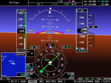
PFD setting (Figure 26)
- Wind Direction, Format 1, Format 2, Format 3, Off
- DME detail On/Off
- BRG1 pointer and databox On/Off
- BRG2 pointer and databox On/Off
- ALT UNIT can be adjusted from FT to M and BARO from in Hg to HPA
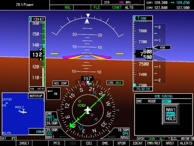
DME (Figure 27)
- NAV1, NAV2, HOLD - Selecting of DME Source. The DME status box will be updated upon DME source selection
XPDR (Figure 28)
- STBY - Standby mode
- ON - On
- ALT - Altitude reporting mode
- GND - Ground mode
- VFR - when toggled on, the transponder will report the default VFR code selected in the Options menu for the NFS software
- ODE - allows the user to enter in the transponder code
- IDENT - cycles the identify feature of the transponder
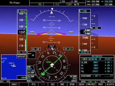
Timer/Reference (Figure 29)
- Timer Value displayed
- UP, DN - Count Up or Count Down
- START? STOP? RESET? - Use ENT to start, stop, and reset
- Reference airspeed values. The values can be edited by the user and the reference flags will be updated on the airspeed tape.
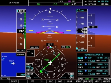
Nearest Airports (Figure 30)
- Nearest airports menu. User can use the FMS knobs to select the airport and press Direct To → Enter → Enter
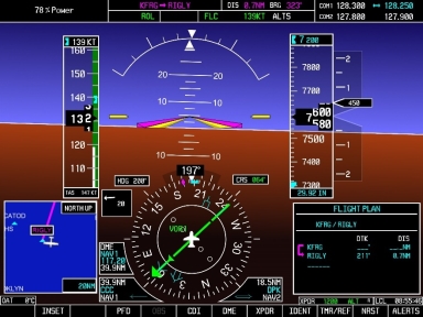
Direct To (Figure 31)
- User can use FMS knob to enter a waypoint

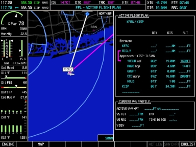
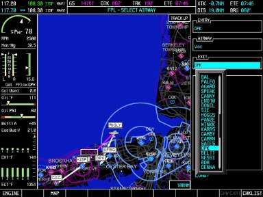
Flight Plan (Figure 32)
- User can use FMS knob to enter waypoints and build a flight plan
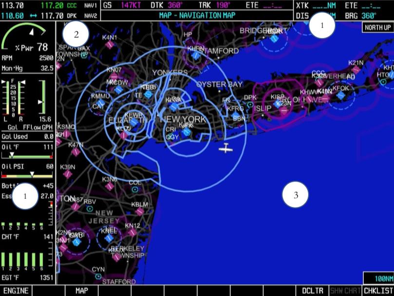
MFD Operations
MFD Components
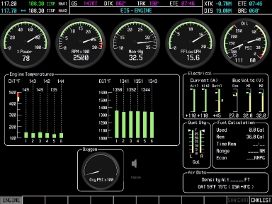
- 1) Engine Indication System (EIS)
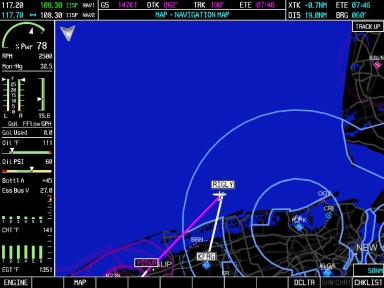
- 2) Moving Map
- 3) NAV1/NAV2 Frequencies
- 4) Data Fields
Note: Please refer to the Garmin Pilot’s User’s Guide for more detailed information
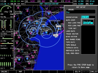
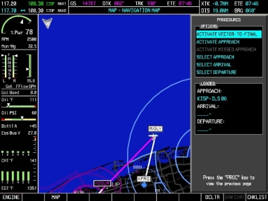
MFD Functions